Enesim Tutorials
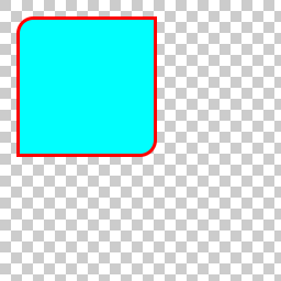
[ tutorial enesim ]This is the first post in a series of tutorial posts for every component on the Enesim project. From Enesim itself to Eon. On this first tutorial we’ll learn how to draw this sample image:
The first step is to create the renderer we want to draw. A renderer is just an abstraction of something that draws, nothing else. It can be a rectangle, a circle a gradient or even a bubble, as long as it draws something we are fine. This is the main difference between Enesim and other graphics libraries, on Enesim there’s no concept of graphics primitives or texturizing, every renderer is both a primitive and a texture.
Let’s begin by creating our rectangle renderer
Enesim_Renderer *r;
r = enesim_renderer_rectangle_new();
The Enesim__Renderer design in a way has an object oriented approach. Every renderer inherits from the base Enesim_Renderer type and so, you can use the generic renderer API to set generic renderer properties. Also note that a rectangle renderer also inherits from a shape and again you can use all the shape API. More on this later.
Now let’s set some common properties
enesim_renderer_origin_set(r, 15.0, 15.0);
enesim_renderer_rop_set(r, ENESIM_BLEND);
In the above code we are setting the renderer origin to 15 on the X axis and 15 on the Y axis. The important thing here is to understand that every renderer has it’s own coordinate system and by setting its origin you are actually translating its center by 15 units.
The rop property is the raster operation. Setting it, informs the system how it should be drawn on a target surface. In this case we are waying that we want to blend the renderer with what is already on the surface.
Now lets set some rectangle properties
enesim_renderer_rectangle_width_set(r, 128);
enesim_renderer_rectangle_height_set(r, 128);
enesim_renderer_rectangle_corner_radius_set(r, 15);
enesim_renderer_rectangle_corners_set(r, EINA_TRUE, EINA_FALSE,
  EINA_FALSE, EINA_TRUE);
The rectangle renderer can have rounded corners, with the above code we are setting the top left corner and bottom right corner to be rounded with a radius of 15. Note that the rectangle renderer uses the origin property as the start of the rectangle, that means that right now we will draw a rectangle of with 128 and height 128 starting at 15 on the X axis and 15 on the Y axis. But what about filling? and stroking?
Given that a rectangle inhertis from a shape, you can use all the shape API to set more properties.
enesim_renderer_shape_fill_color_set(r, 0xff00ffff);
enesim_renderer_shape_stroke_color_set(r, 0xffff0000);
enesim_renderer_shape_stroke_weight_set(r, 3.0);
enesim_renderer_shape_draw_mode_set(r, ENESIM_SHAPE_DRAW_MODE_STROKE_FILL);
So now we are setting the fill color to ARGB(255, 0, 255, 255) the stroke to ARGB(255, 255, 0, 0) and the width or weight of the stroke to 3. Even if those properties are set, it does not mean that we will actually draw with such fill/stroke configuration. We need to set the drawing mode we are going to use, being it fill only, stroke only or both. For this case we will use stroke and fill. Note that we are not using any alpha different than 255 (i.e full opaque) to simplify this description. Every color used on Enesim has to be premultiplied by its alpha, but no worries about that, we do have some helper functions that transform an ARGB value to a premultiplied ARGB value.
Now that we have all the renderer set up, we want to actually draw it. For that we create an Enesim_Surface. A surface is just a pixel area where you can actually draw your renderer. On some systems this is called Drawable, on other Pixmaps or Textures.
Enesim_Surface *s
s = enesim_surface_new(ENESIM_FORMAT_ARGB8888, 256, 256);
So, you have created an ARGB surface with 8 bits per component of size 256 x 256. Now the real drawing
enesim_renderer_draw(r, s, NULL, 0, 0);
Note that we haven’t set all the parameters for simplicity. But I will explain them too. The first argument of course is the renderer you want to draw and the second one the target surface you want to draw, those were easy. The third one defines the clipping area you want to draw on the destination surface and the last two is the origin of the destination surface. Remember that every renderer has it’s own coordinate space? in this case a surface does have it too. It is always from 0 on the X axis and 0 on the Y axis and the width and height are the same as the surface width and height. With the two last arguments you can translate the surface origin, but to make this initial tutorial simple we wont describe the whole functionality, yet! :)
The complete code can be found here